Understanding LPDDR4 bus behavior can be a daunting task. LPDDR4 introduces a new way of transmitting command and address data across the bus involving multiple clock cycles to transmit the information required. Fortunately, the MA5100 Memory Analyzer provides clear, detailed command displays and helpful features to allow easy viewing and navigation over deep acquisition data.
In this video we will look at LPDDR4 command structure and the features that support them in the MA5100 memory analyzer from Nexus Technology. We will look at the various ways these commands are displayed. We will also look at search and filter capabilities available in the analyzers.
LPDDR4 Command Structure
LPDDR4 commands follow a pattern that was established by LPDDR3 in that the information is transmitted on Command/Address or CA bits. LPDDR4 differs in that the CA bits are transmitted on successive rising edges of the clock. A command starts on the rising edge of the clock where a chip select is high. This cycle is referred to as a primary command cycle as it determines what will follow next. Most commands continue on the next rising edge of the clock. These commands are indicated by the chip select which will be low. We refer to this as a continuation cycle as it ‘continues’ to send information on the command. This two-cycle command sequence is standard for almost every LPDDR4 command.
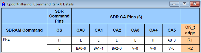
A precharge (PRE) command is a good example of a typical two-cycle command.
Some commands require additional information that will not fit in the primary and its ‘continue.’ Activate (ACT), read (RD), write (WR) and masked-write (MWR) commands are good examples. These commands require a total of four cycles to complete. These commands follow a pattern identical to two, contiguous two-cycle commands. For example, an activate (ACT) command is four cycles but could be considered two contiguous two-cycle commands, referred to as ACT-1 and ACT-2.
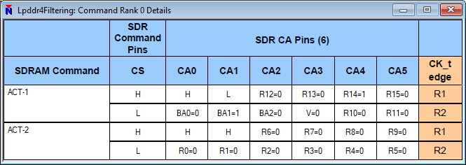
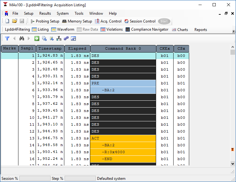
In the MA5100 series analyzer, commands are show in both a listing window and a waveform window. In the waveform, they are shown in mnemonic format as we are looking at bus activity. Additional detail is shown in the listing. Since listing and waveform track together, even when looking at the waveform display, the detail in the listing is still available. For detailed information about exactly how the command appeared on the bus, you can right-click on the command in either the listing or waveform and select ‘Command Detail’. This gives us a breakdown of exactly what appeared where in the command transmission. You can see here, we start with the primary command – ACTIVATE-1 – where CS0 went high and we got a rising edge of the clock. This was followed by a ‘continue’ with CS0 going low with another rising clock edge. This is followed by the secondary command, ACTIVATE-2, with CS0 going high at the rising clock edge. This is followed by the ‘continue’ with CS0 going low with another rising clock edge. You can see in the display exactly what information was sent on which CA bit during each bus cycle. This is one way you can see the source of the information being displayed in the listing and waveform.

There are many commands that can be sent on the bus. Here is a list of the standard commands.
| Command | CKE_prev | CKE | CS | CA0 | CA1 | CA2 | CA3 | CA4 | CA5 | Rising Clock Edge |
| WR | H | H | H | L | L | H | MASK | L | BL | 0 |
| H | H | L | BA0 | BA1 | BA2 | V | C9 | AP | 1 | |
| H | H | H | L | H | L | L | H | C8 | 2 | |
| H | H | L | C2 | C3 | C4 | C5 | C6 | C7 | 3 | |
| RD | H | H | H | L | H | L | L | L | BL | 0 |
| H | H | L | BA0 | BA1 | BA2 | V | C9 | AP | 1 | |
| H | H | H | L | H | L | L | H | C8 | 2 | |
| H | H | L | C2 | C3 | C4 | C5 | C6 | C7 | 3 | |
| MRW | H | H | H | L | H | H | L | L | OP7 | 0 |
| H | H | L | MA0 | MA1 | MA2 | MA3 | MA4 | MA5 | 1 | |
| H | H | H | L | H | H | L | H | OP6 | 2 | |
| H | H | L | OP0 | OP1 | OP2 | OP3 | OP4 | OP5 | 3 | |
| MRR | H | H | H | L | H | H | H | L | V | 0 |
| H | H | L | MA0 | MA1 | MA2 | MA3 | MA4 | MA5 | 1 | |
| H | H | H | L | H | L | L | H | C8 | 2 | |
| H | H | L | C2 | C3 | C4 | C5 | C6 | C7 | 3 | |
| REF | H | H | H | L | L | L | H | L | L (AB) | 0 |
| H | H | L | BA0 | BA1 | BA2 | V | V | V | 1 | |
| REFA | H | H | H | L | L | L | H | L | H (AB) | 0 |
| H | H | L | BA0 | BA1 | BA2 | V | V | V | 1 | |
| ACT | H | H | H | H | L | R12 | R13 | R14 | R15 | 0 |
| H | H | L | BA0 | BA1 | BA2 | V | R10 | R11 | 1 | |
| H | H | H | H | H | R6 | R7 | R8 | R9 | 2 | |
| H | H | L | R0 | R1 | R2 | R3 | R4 | R5 | 3 | |
| SRE | H | H | H | L | L | L | H | H | V | 0 |
| H | H | L | V | V | V | V | V | V | 1 | |
| SRX | H | H | H | L | L | H | L | H | V | 0 |
| H | H | L | V | V | V | V | V | V | 1 | |
| PRE | H | H | H | L | L | L | L | H | L (AB) | 0 |
| H | H | L | BA0 | BA1 | BA2 | V | V | V | 1 | |
| PREA | H | H | H | L | L | L | L | H | H (AB) | 0 |
| H | H | L | BA0 | BA1 | BA2 | V | V | V | 1 | |
| MPC-T | H | H | H | L | L | L | L | L | H | 0 |
| H | H | L | OP0 | OP1 | OP2 | OP3 | OP4 | OP5 | 1 | |
| MPC-NOP | H | H | H | L | L | L | L | L | L | 0 |
| H | H | L | X | X | X | X | X | X | 1 | |
| DES | H | H | L | X | X | X | X | X | X | 0 |
| PDE | H | L | X | X | X | X | X | X | X | 0 |
| PD | L | L | X | X | X | X | X | X | X | 0 |
| PDX | L | H | X | X | X | X | X | X | X | 0 |
Searching for Commands

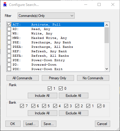
The search feature may be accessed with the binoculars button. Notice the arrow buttons on either side of the binocular button are initially disabled since we have not yet defined search criteria. By clicking on the binoculars button, you can configure your search. In this example, we will search for only activate commands. There are many options to restrict the search down to specific ranks or banks. Once a search is defined, the previous and next arrow buttons are be enabled.
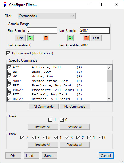
Filtering Commands from Display
Another feature available in the analyzer is filtering which is accessed by clicking the funnel button. Filters can restrict by sample range, which is helpful if we want to focus on a subset of the acquisition data. A good example use case of filtering may be to restrict the display to only show valid commands. In other words, filter idle and deselect cycles from the display. This is accomplished by filtering by Command(s).
Further Information
All the information found here is also covered in the video. You can find more information on the MA5100 Analyzer Product page.